Paper-less and "star-less" navigation, using a bubble sextant in Flight Simulator.
(
A modified version that works with FSX can be downloaded from here.).
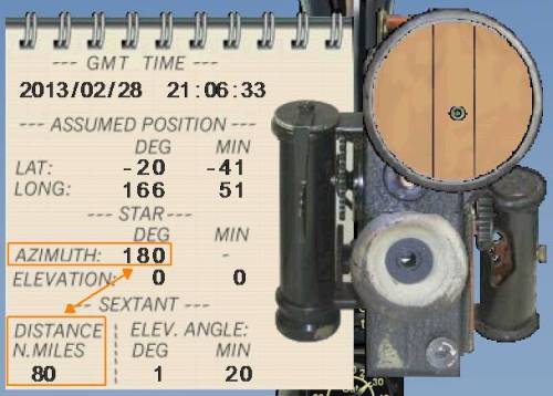
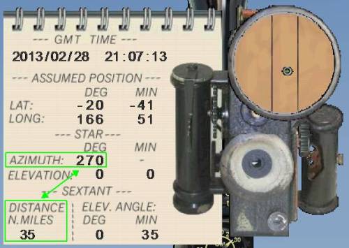
A big part of the workload, when using a sextant, is looking up star positions for the current location and time. With the sextant available in Flight Simulator it is possible though, to skip this step, and to just "pretend" there is a star at the desired location, and the returned values will be just as accurate.
The basic concept of operating the sextant, and navigating with the found data, is the same as when using real star positions; it just saves a bit of the grunt work.
For the purpose of this tutorial we will place the aircraft stationary at an airport
(so we don't have to worry about moving around while following the steps),
and use as our
assumed position a location about 90nm NE of the
actual position.
This tutorial assumes that you know how to do the basic operations of this sextant
(e.g. entering coordinates, and adjusting the elevation). For details on those operations,
please refer to the original manual.
|
Method using Google Earth
|
| 5. |
Open Google Earth, and put a placemark at the assumed position.
|
| 6. |
Activate rulers (Tools | Ruler), select the Line tab,
and set units to nautical miles.
Make sure that that north is straight up (press "G" to align, if it isn't.).
|
| 7. |
Click on the assumed position, and drag a vertical line down,
at the length of the 180� distance (if negative, draw the line up).
|
| 8. |
Select the handle at start of the line (at the assumed position),
and drag it to left of the end marker (to indicate the 270� distance).
(The Ruler window will show the heading as 90�, but that's ok,
as it's considering the moved point to be the origin.)
If the distance was negative, drag it to the right instead.
The final point is your actual position.
|
| 9. |
You could now drag the intermediate point (on the right) back
onto the assumed position, and the ruler window will give the
distance and (true) heading between these two.
|
"Classic" method, using PLan-G
|
| 5. |
Open Plan-G, and place a user waypoint at the assumed position.
|
| 6. |
Set the range ring distances, so that they come close to both
of the distance measurements.
Depending on the returned values you might need 2 or 3 rings, in order to
match the distances.
In our example, we have 35 & 80nm, so we use two rings at a radius of 40nm.
|
| 7. |
Display range rings around the assumed position
|
| 8. |
Open IrfanView (or any other bitmap editor), and take a screenshot of the map.
|
| 9. |
If the 180� distance was positive, draw a line south from the assumed position
(if negative, go north), using the range rings as a guide for the correct length.
|
| 10. |
If the 270� distance was positive, draw line to west (if negative, go east),
again using range rings to estimate the correct distance.
In our example, both values were positive:
|
| 11. |
Draw a perpendicular line at the end of each of the two distance vectors.
Where these two lines cross is your actual position:
|
Method using sextant chart gauge
An expansion to the sextant gauge, in the form of an attached chart
(which is included in the FSX update), can be used as described below:
|
| 5. |
Use the same coordinates as in the example above.
|
| 6. |
Once the distance has been established, click the "STAR-1" button on the chart.
This will display a blue line, at the specified azimuth (180�):
|
| 7. |
Take a measurement for azimuth 270�, and click the "STAR-2".
|
| 8. |
This adds a green line to the chart (at 270�).
|
| 9. |
Take an additional measurement for 225�, and click the "STAR-3" button.
|
| 10. |
This adds a red line to the chart (at 225�).
|
| 12. |
Move the green circle from the center of the chart to where those three lines meet, using the green arrow buttons at the side and bottom of the chart.
The plane's corrected coordinates are now shown at the X and Y-axis:
-21� -55', 166� 18' (which is within 10nm of the actual position).
|


